click to see larger version (~80kByte)
Last
updated: 29. Feb 2000
Changes:
the 2uF cap will be charged to higher voltage; safer triggering circuit
for the BT152; ...
DISCLAIMER: This device is dangerous and can cause damage of property and health or even death. I cannot take any responsibilty for any damage possibly resulting from using the device described here, or following the instructions given (nor for anything else you do!). So be careful, follow safety instructions and use common sense.
click to see larger version
(~80kByte)
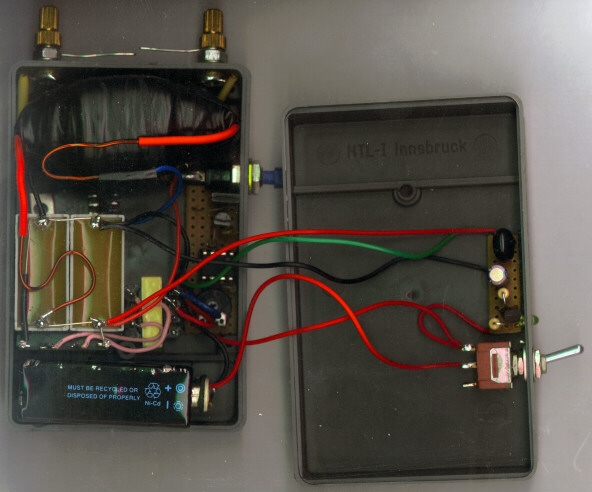
This device is really small (10cm x 5cm x 3cm). It produces 5mm to 10mm long sparks at high power. The output voltage must be bigger than 8kV, because I killed an 8kV cap with this unit! WARNING: Touching the contacts (on top of the picture) and pressing the "fire" button is really painful (I tried it myself...the 2uF cap was only charged to 500V. I'm not crazy enough to touch the contacts after the 2uF cap is charged to 740V)
Basically, I'm discharging
a cap of 2uF @ 740V through a self made ignition/trigger coil.
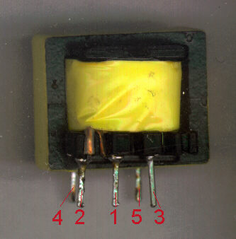
The coil (Tr2) has a ferrite
core which is 4cm long and has 1cm diameter. On the primary side of the
coil there are 15 turns of 1mm wire. On the secondary side there are about
400 turns of thin wire. I wound the secondary over the primary windings.
I used a lot of insulation tape between every layer of the HV-windings.
Between the primary and the secondary layers there are a shrinking tube
and an insulation tape.
On the right side of this circuit diagram you can see the 555 timer IC (NE555, LM555, ...). The frequency of the 555 should be adjusted to 15kHz. If you can't set the frequency down to 15kHz, use a bigger capacitor between pin 6 of the 555 and ground. The Tr1 is a fotoflash transformator 3V => 230V. I'm driving it with 9V :-). Click here for a picture of it. Br1 is a bridge rectifier, but you can use four 1N4007 diodes instead of it. The BT152 is a 800V, 20A Thyristor. You can use every other type which can handle the voltage (about 740V) and the high current while discharging the 2uF cap. The 2uF cap should be a foil cap which can handle more than 700V and the high current pulses. Don't use electrolytic types, because their inductivity is higher than the inductivity of the foil caps => higher inductivity, less discharging current.
 The
mobile HV-Pulse generator will work without the voltage regulation circuit,
but do NOT leave it out, because it protects every part behind the Tr1
from overvoltage and it saves battery power. The LED will show you that
the maximum voltage has been arrived, but it doesn't light up, when the
power is off and the cap(s) are charged. The voltage of the 10uF cap need
not to be high, I'm using a 50V version of it. The varistor I used was
a S05K460. With this varistor the cap will be charged to 740V.
The
mobile HV-Pulse generator will work without the voltage regulation circuit,
but do NOT leave it out, because it protects every part behind the Tr1
from overvoltage and it saves battery power. The LED will show you that
the maximum voltage has been arrived, but it doesn't light up, when the
power is off and the cap(s) are charged. The voltage of the 10uF cap need
not to be high, I'm using a 50V version of it. The varistor I used was
a S05K460. With this varistor the cap will be charged to 740V.
.
.
Helpful hints: