| Jochen's High Voltage Page |
The marx generator in its current state has 10 stages, each consisting of
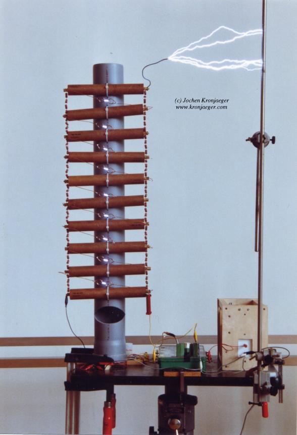 |
Time exposure of several discharges of the marx generator. The ladder-like construction is the actual generator, the caps are mounted horizontally on the grey PVC tube. Vertically, left and right from the caps, are the resistor chains. The gaps are simply bent wires. The vertical metal rod to the right is grounded. The remaining stuff is the charging system, a flyback driving a TV cascade. Click on image for larger version. |
Using a flyback driver with a subsequent TV multiplier and a 1MOhm charging resistor, the repetition rate is roughly once per second.
In a first version, the spark gaps were made of about 1mm diameter copper wire, which was bent into a ring (about 2cm diameter) to prevent corona and premature breakdown. For optimal operation, all gaps should be equally wide. (Some say that the frist gap should be somewhat less wide, but for me it also works if they are all equal. Maybe this has some drawback that I have not yet noticed.). Adjustment is done by slightly bending the wires until a rod or tube of suitable diameter just fits through.

|
Schematic drawing of the marx generator with "wire gaps". |
While this construction was chosen as a quick fix and proved useful, disadvantages of this "wire gap" are obvious:
The improved version makes use of 1cm diameter spherical nuts on M6 screws. The gaps are thus easily adjustable and should be stable at their position. The gaps are mounted into a cable duct with a lid which can be opened or closed, depending on whether you want the gaps visible or not.

|
Schematic drawing of the improved spark gap. For each stage, one such gap is mounted in the cable duct. The whole structure is then attached to the marx generator and wired to the caps. |
In the first version, the charging resistors consisted of a string of four 2kOhm 2Watt carbon film resistors each. This relatively low resistance of 8KOhm allowed for rapid charging and low voltage drop due to corona and other leakage currents, but also caused the output voltage pulse to decay with a time constant of around 30us. The achievable spark length was thus limited by the short duration of the pulse to around 30cm. Also, the resistors were operated far beyond their design voltage (probably 500V) and frequently broke down, in particular when the output was accidentally "open", i.e. a spark did not develop and the whole energy stored had to be dissipated by the resistors.
The improved version uses two commercial high voltage resistors (Vishay HGR0939, 1MOhm, 5kV, bought via ebay) in series, resulting in much improved reliability and an increased falling edge time constant of 8ms. As a drawback, the charging time is also much longer and the "fire rate" lower, and corona losses are noticable now.
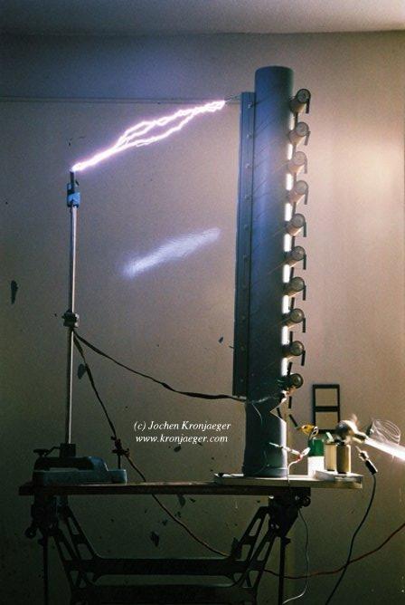 |
10-stage marx generator with improved spark gaps and 20MOhm charging resistors. The distance between the main discharge electrodes is 40cm. Taking into account that the actual peak voltage is probably less than 10x the charging voltage (30kV), this already comes close to the maximum spark length expected between needle electrodes. Click on image for larger version. |
The maximum discharge length depends on the value of the resistors connecting each stage. The larger this value, the longer the possible distance, up to some expected optimal value at least. Possible explanation: Once the gaps are in the conducting state, the caps begin to discharge through these resistors. At the same time, a spark starts to develop at the output terminal. This takes the longer the bigger the distance to ground is. If the caps discharge too quickly through the resistors, the spark has not enough time to fully develop. With the current values of R and C, the characteristic time is 8ms.
The discharge seems to induce huge voltage transients in ground and/or mains leads. This has resulted in a burnt mains switch and a destroyed ground fault interrupter. Grounding the marx generator seperately and decoupling the charging voltage ground with a resistor helps somewhat. This may turn out to be a major problem, as the marx generator naturally produces a huge voltage step with a risetime probably in the microsecond range, and the subsequent discharge produces a similarly steep current pulse which might be kA or more.
| [Index] | [Links] |
© 2000-2006 Jochen
Kronjaeger
Email: ![]()
Last modified: 2004-12-30 16:16:48
This document is copyrighted. All rights reserved. No part of this document may be reproduced without my permission. Permission to copy and publish this document or parts of it on the WWW is granted until explicitely revoked, under the condition that it is accompanied by this or a simliar copyright notice, including my name and the original URL.